
Circuit Board, Multiplexer
Project
Add a signal multiplexer to an existing car security system by matching signal forms.
Following a car break-in, several security devices were added to my car which exceeded the signal input capacity that the existing alarm system could handle. Trunk, hood, and decoy alarm signals were added, however, only one auxiliary input was available on the car alarm.
This project required circuit design, PCB design, layout, component selection, PCB population, hardware mounting, and hardware installation.
Solution
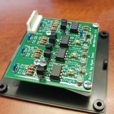
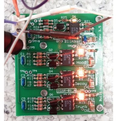
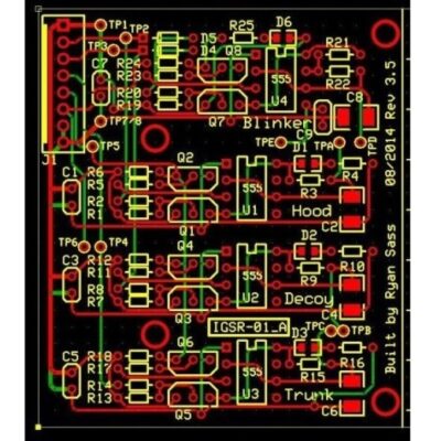
A three-signal multiplexer circuit was developed and the discrete components were populated onto a custom-designed circuit board. This multiplexer circuit can take the trunk, hood, and decoy switch signals, and trigger the alarm from only one input.
One issue that was handled is that after a given signal stays on, it can block the auxiliary alarm signal unnecessarily. The circuit I designed will reset the auxiliary signal to the alarm after a given time to ensure multiple signals can trigger the alarm. Finally, an indicator light of the auxiliary switch state was incorporated into existing dashboard lights to provide state feedback on the switches.
Result
The car alarm multiplexer works spectacularly. During a trunk, hood, or decoy switch activation, the alarm triggers and will trigger when another switch is activated. When the hood is left open or the decoy switch is activated, the indicator light on the dashboard flashes to give the user state feedback and not be confused with the original purpose of the light on the dashboard. It has thwarted a potential break-in since installation due to alarm activation.
