
MQTT Client and Remote Switch
Project
This project came about due to a need to remotely manipulate the Power and Reset switches of a PC, allowing remote power on, wake up, resetting, and hard power down control.
The need for this came about because of a personal desire to remotely access my PC via remote desktop combined with my desire to save energy by powering off/sleeping a computer when not in need, but also to provide full power control of the PC, even while remote.
While sending “magic packets” to wake the computer is a solution, it would not provide the reliability, feedback, and versatility required. Because of this, it was decided to utilize an Arduino board with WiFi capability as an IO device to interface between the computer and the internet. The Arduino would connect to a user via MQTT protocol to receive user commands and report Arduino board state.
Solution
The solution consists of five separate developments- solution architecture, software development, shield and breakout board design/layout, shield and breakout board circuitry design, and mechanical mounting development.
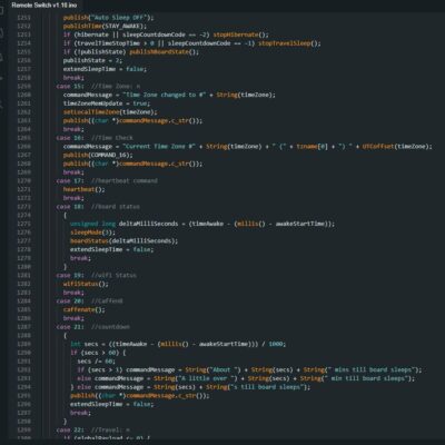
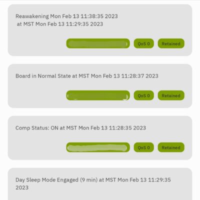
An ESP8266F Arduino board running a C++ variant code was used. To interact with the board remotely, the Arduino was programmed to configure as an MQTT client, and through WiFi connected to an MQTT broker. This allows commands to be sent to and status reports received from the Arduino board. This MQTT protocol also allows pending commands to be stored on the MQTT broker, allowing for commands to be retained and await successful arduino board connection.
For architecture design, the entire project had to be designed in a way to connect to both the computer, the internet, as well as a preexisting UI client interface to receive commands.
For software development, the board had to be coded in a way to be resilient during any sort of power loss and remember any existing commands or instructions given to it. It also had to access its own onboard memory to remember certain operational configurations, including what NPT time zone it was configured to to timestamp messages. All of this had to be coded into the schema of how the board operated.
For electronics design and board layout, the boards were designed to minimalize power consumption, minimize board footprint, as well as utilize normal components to allow for connections. This board utilized optoisolators to directly connect to and trigger the computer power and reset switch signals as well as receive feedback signals of the computer’s power status. This allowed the board to record and report if the computer is OFF, ON, or Sleeping.
For mechanical design, 3d printed designs which utilized simple mounting techniques, as well as interchangeable parts to reduce printing and design spin time were utilized to speed production.
Results
Using over 2300 lines of code, the board works very well, resuming operation during power resets and allowing full remote operation. While the board and computer were left in the SF Bay Area, the operation and awakening of the computer have been tested as far away as Japan! This includes updating the time zone the board operates in (it goes to sleep during the ‘night’) to JST successfully.
To get time, the board connects to NPT servers, to carry accurate time information, allowing it to timestamp any messages. This also allows the board to ‘deep sleep’ during times of planned non-operation and then return to an operation state thereafter.
Some of the other notable features of the board include recording the last known status of the computer and how long it has been in that state, ‘sleeping’ for planned durations well past the board’s maximum allowed deep sleep (due to the RTC memory limits), and staying ‘caffeinated’ during times of planned sporadic need so that the board remains on.


